Vhdl Program For Parity Generator Image
Vhdl Program For Parity Generator And Parity. Erweiterung Was; 000 (000-600) Paperport Scanned Image. Here are few programs i want to make open source for u. Jul 17, 2012 - VHDL code for 4-bit Parity Checker. Library ieee; use ieee.std_logic_1164.all; entity parity_checker is port ( a0: in std_logic; a1: in std_logic; a2: in std_logic; a3: in std_logic; p: out std_logic); end parity_checker; architecture parity_checker_ar of parity_checker is signal r,s: std_logic; begin --. Oct 28, 2013 - Design and Test Bench code of 8x3 Priority Encoder is given below. Output are set ac. Design 8 bit Ripple Carry Adder using VHDL Coding and Verify using Test Bench. Given below code will generate 8 bit output as sum and 1 bit carry as cout. It also takes two 8 bit inputs as a and b, and one input ca. In VHDL code, given the methods (below) for calculating 8-bit parity, write a VHDL program that MAXIMIZES CONCURRENCY (dataflow) for parity calculation of 1024 bits. The given methods would not maximize concurrency if extended out to 1024 bits because in each case is completely dependent on each and every bit.

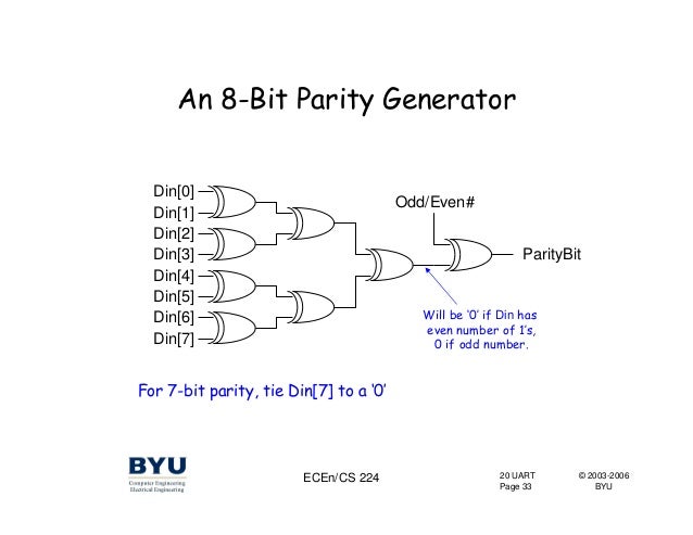
In VHDL code, given the methods (below) for calculating 8-bit parity, write a VHDL program that MAXIMIZES CONCURRENCY (dataflow) for parity calculation of 1024 bits. The given methods would not maximize concurrency if extended out to 1024 bits because in each case is completely dependent on each and every bit previous. --Parity Architecture 1-- ARCHITECTURE parity_dataflow OF parity IS SIGNAL xor_out: std_logic_vector (7 downto 1); BEGIN xor_out(1). Hence, parity bit is added to the word containing data in order to make number of 1s either even or odd.Thus it is used to detect errors, during the transmission of binary data.The message containing the data bits along with parity bit is transmitted from transmitter node to receiver node. At the receiving end, the number of 1s in the message is counted and if it doesn’t match with the transmitted one, then it means there is an error in the data. Steve Reich Vermont Counterpoint Pdf Download. Parity generator and checker A parity generator is a combinational logic circuit that generates the parity bit in the transmitter. On the other hand, a circuit that checks the parity in the receiver is called parity checker.
A combined circuit or devices of parity generators and parity checkers are commonly used in digital systems to detect the single bit errors in the transmitted data word. The sum of the data bits and parity bits can be even or odd. In even parity, the added parity bit will make the total number of 1s an even amount whereas in odd parity the added parity bit will make the total number of 1s odd amount.
Recycle Greatest Hits Of Spitz Best Of Rar. The basic principle involved in the implementation of parity circuits is that sum of odd number of 1s is always 1 and sum of even number of 1s is always zero. Such error detecting and correction can be implemented by using Ex-OR gates (since Ex-OR gate produce zero output when there are even number of inputs). To produce two bits sum, one Ex-OR gate is sufficient whereas for adding three bits two Ex-OR gates are required as shown in below figure.
Parity Generator It is combinational circuit that accepts an n-1 bit stream data and generates the additional bit that is to be transmitted with the bit stream. This additional or extra bit is termed as a parity bit. In even parity bit scheme, the parity bit is ‘ 0’ if there are even number of 1s in the data stream and the parity bit is ‘ 1’ if there are odd number of 1s in the data stream. In odd parity bit scheme, the parity bit is ‘ 1’ if there are even number of 1s in the data stream and the parity bit is ‘ 0’ if there are odd number of 1s in the data stream. Let us discuss both even and odd parity generators. Even Parity Generator Let us assume that a 3-bit message is to be transmitted with an even parity bit. Let the three inputs A, B and C are applied to the circuits and output bit is the parity bit P.
The total number of 1s must be even, to generate the even parity bit P. VHDL Code for Parity Generator using Function. When valid_in is '1' it will accept serial input and that.
After valid_out goes high parity_out signal gives parity of the input data Rust Colored Stones Rar. . Valid_out signal goes high on each eighth clock cycle. 24, return (i(0) xor i(1) xor i(2) xor i(3) xor i(4) xor i(5) xor i(6) xor i(7)). VHDL Examples EE 595 EDA / ASIC.. Odd Parity Generator. --- goes high then there is a loop which checks for the odd parity by using--- the xor logic.There is.